PECO Harmonic Energy Recycling Transformer
The core energy-saving component inside every PECO Powersaver — a three-phase zig-zag autotransformer designed, above all, not to get hot.
One Component Does the Work
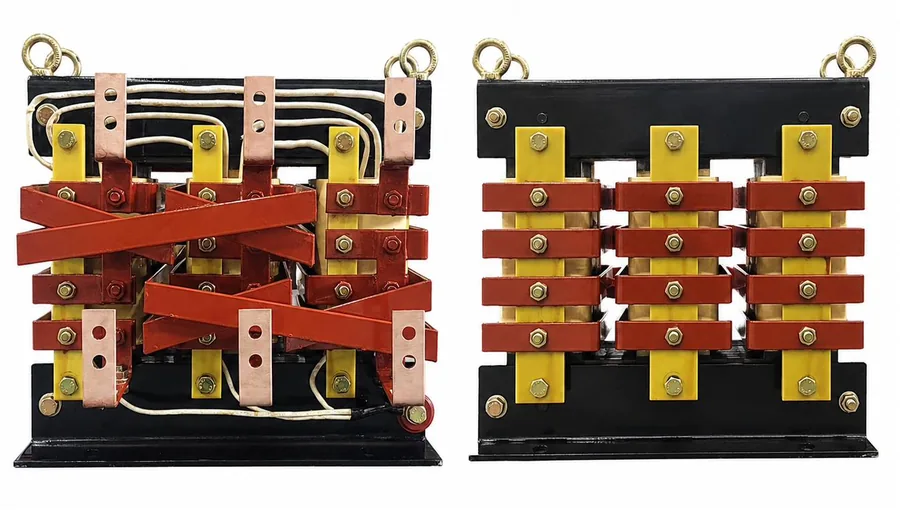
PECO Powersaver is a system, but only one part of it saves energy. The Harmonic Energy Recycling Transformer is a three-phase, three-wire zig-zag autotransformer, connected in series between the main circuit breaker and the sub-distribution boards. Everything else in the cabinet exists to protect it, switch it or display its operating values.
It contains no electronics, no control algorithm and no moving parts. It operates magnetically, continuously, for the life of the installation.
- Three-phase, three-wire
- Zig-zag winding
- H-class insulation
- AN cooling
- Korean Patent 10-2546570
A Note on Terminology
Equipment of this type is commonly referred to as voltage optimisation, or simply as an energy saving transformer. PECO Powersaver belongs to that category.
What distinguishes it is the design objective. Conventional equipment in this category is built primarily to step the voltage down. PECO was built to solve a different problem — how to place a transformer in series with a facility’s supply without the resistive loss and heat that a series element normally brings.
The Problem: A Series Element Costs Something
Any device connected in series with a facility’s supply carries the full load current. That current meets the resistance of the device’s own winding, and the result is loss and heat.
In a conventional passive zig-zag autotransformer the whole winding is a continuous tapped common winding. All of it carries load current, and its resistance sets how hot the device runs. That heat has to be removed, which is why equipment of this type is often built around its cooling arrangement rather than around its winding.
PECO was designed the other way round.
We set out to stop it getting hot.
It turned out to save more.
01 / Low-Heat Winding Design
Reducing Heat in the Winding, Not at the Fan
A conventional passive autotransformer winds 96 turns and adds four to reach 100. One continuous winding, with the 4 % step-down taken from a tap along it — the same winding both excites the core and provides the step-down.
PECO winds a full 100, then adds four more, wound in reverse as a separate winding and tied to the main winding at both ends.
The step-down is the same 4 %. More conductor is used, current density is lower, and the series element adds very little resistance — and very little heat. Ventilation handles what remains, rather than compensating for a design that runs hot.
More conductor, for the same rating. A PECO transformer is heavier than one built the conventional way — a deliberate choice, not an accident of manufacture.
Allowable winding temperature 130 °C · H-class insulation · AN (air natural) cooling
Patented winding architecture
Korean Patent No. 10-2546570
Zigzag Winding Transformer for Saver to Supply AC Power
02 / Nine-Point Zig-zag Interconnection
Nine Transition Points, Where a Conventional Arrangement Has Six
A zig-zag winding works by carrying each phase’s output through winding sections that sit on different core limbs. Each time the path crosses to another limb, that is a transition point.
In PECO, the main winding zig-zags across all three phases — three transition points. The auxiliary winding zig-zags across two — three more. That gives six, as in a conventional arrangement.
Tying the two windings together at both ends adds three further transitions. Nine in total. The phases are interlinked more finely than a conventional zig-zag allows.
What This Does Not Mean
PECO is not a harmonic filter, and it does not generate energy.
The winding architecture was designed to do one thing: place a series element in the distribution system without the resistive loss and heat that a series element normally brings. Everything else follows from that.
The name Harmonic Energy Recycling Transformer describes the design intent of the winding. It is not a claim that energy is created.
A Device in Series Must Not Cost More Than It Saves
This is the first question an electrical engineer should ask about any series-connected device, and it deserves a number rather than a reassurance.
Transformer efficiency: typically 99.8 % or higher
99.7 % – 99.83 % across measured models
Two things keep it there. The winding architecture described above adds very little resistance to the series path. And in an autotransformer with a 4 % voltage difference, only a small fraction of the throughput power is magnetically transformed — the remainder passes through conductively.
The physical evidence is the transformer itself.
| Rating | Transformer weight | Weight per kVA |
|---|---|---|
| 300 kVA | 180 kg | 0.60 kg |
| 1,000 kVA | 356 kg | 0.36 kg |
| 2,000 kVA | 502 kg | 0.25 kg |
| 3,000 kVA | 652 kg | 0.22 kg |
Weights are indicative and vary with rated voltage and winding configuration; full dimensions and weights are published on the specifications page.
The ratio falls as rating increases, because the transformed portion of the power stays proportionally small while the conductive path carries more. A two-winding transformer of the same throughput rating has no such advantage — it must transform all of the power, and would weigh several times more.
Against a conventional autotransformer of the same rating, the comparison runs the other way: a PECO transformer is heavier, because it uses more conductor. Both statements are accurate, and they are not in conflict — they are comparisons against different equipment.
Efficiency figures are taken from the product manuals supplied with each unit. Dimensions and weights are published in full on the specifications page.
Balancing the Load Between Phases
The output of each phase is formed from winding sections associated with the other phases, offset by 120°. The zig-zag interconnection therefore couples the phases magnetically rather than treating them independently.
Where a facility carries unequal loading between phases — common in buildings where single-phase circuits have been added over time — this coupling tends to reduce the imbalance seen upstream. Unbalanced current produces losses that do no useful work. Reducing it reduces those losses.
Fixed at 4 %, Without Tap Changing
PECO maintains an output of approximately 96 % of the input voltage. The ratio is fixed by the winding design. There is no tap changer, no adjustment mechanism and no control loop — nothing that can drift, fail or require commissioning.
Output ≈ Input × 0.96
Example: 415 V → 398.4 V
For a nominal 400 V system, this output remains within the supply voltage range permitted by EN 50160 and IEC 60038. Input tolerance is 415 V ±7 %.
The 4 % difference is a design condition of the winding architecture described above. It is not, on its own, the explanation of the energy-saving result — and any supplier presenting it as such is describing a simpler device than this one.
The objective is not weaker load operation.
It is lower accumulated energy consumption for the same operating task.
A Note on Harmonics
Reduction of fifth- and seventh-order harmonic current is characteristic of zig-zag energy-saving transformers generally. PECO differs in degree rather than in kind: the main and auxiliary windings are tied at both ends, and the auxiliary path carries more current at lower resistance than its own conductor would allow.
We do not publish harmonic reduction figures, and PECO is not offered as a harmonic filter. Where a facility has a specific harmonic requirement, it should be addressed with equipment designed for that purpose.
Where PECO Fits — and Where It Does Not
PECO is not suitable for every installation. Identifying that before a proposal is made saves everyone’s time.
Where results have been strongest
- Facilities where large motors are driven through inverters — compressors, pumps, fans
- Forging and metal processing plant
- Continuous or multi-shift industrial operation
As inverter drives become standard on large motors, this is an increasing share of industrial and commercial load.
Well suited
- Facilities operating long hours with continuous mixed loads
- Motor-driven plant: HVAC, chillers, pumps, fans, lifts
- Lighting and resistive loads
- Systems with measurable imbalance between phases
- Central low-voltage distribution with a single main supply point
Limited or not recommended
- Systems where supply voltage already operates near the lower limit of the permitted range
- Very low load factor, or highly intermittent operation
- Distribution arrangements that cannot accommodate a series-connected device
Suitability is confirmed by reviewing the single-line diagram, transformer rating, voltage range and load composition — before any proposal is made.
See How It Works in the System
The transformer described here is one part of the PECO Powersaver system. How it is connected, protected and switched — and how its effect is measured — is covered on the following pages.