Commercial & Industrial Energy Saving
Passive Energy Saving System
Powered by Harmonic Energy Recycling Transformer Technology
PECO Powersaver is a series-connected transformer built to add almost no resistance of its own. Its patented winding uses more conductor than the conventional arrangement, which keeps loss and heat low — so the system reduces accumulated energy consumption without modifying any connected equipment.
- Low-Heat Winding Design
- Nine-Point Zig-zag Interconnection
- Verified in kWh
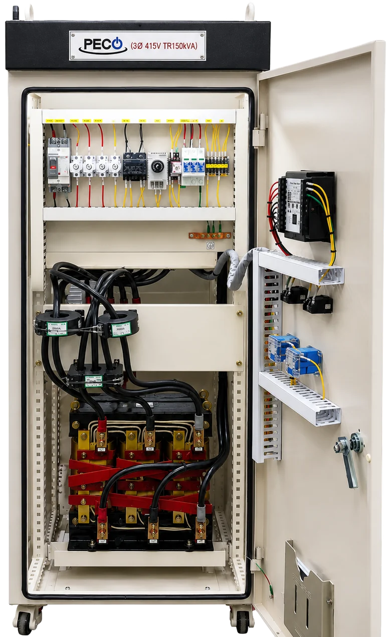
Position in the distribution system
- Main Transformer
- Main Circuit Breaker
- PECO Powersaver
- Distribution Boards
- Facility Loads
- Assessed by TÜV SÜD
- 100–3,000 kVA
- Transformer efficiencyEfficiency typically 99.8 % or higher
- Korean Patent 10-2546570
- Manufacturing since 1999
Built to Stay Cool. It Turned Out to Save More.
The design objective was not a saving percentage. It was to put a transformer in series with the supply without the resistive loss and heat that normally comes with it.
01 / Low-Heat Winding Design
Reducing heat in the winding, not at the fan
A conventional passive autotransformer winds 96 turns and adds four to reach 100. One continuous winding, with the 4 % step-down taken from a tap along it — the same winding both excites the core and provides the step-down.
PECO winds a full 100, then adds four more, wound in reverse as a separate winding and tied to the main winding at both ends.
The step-down is the same 4 %. More conductor is used, current density is lower, and the series element adds very little resistance — and very little heat.
More conductor, for the same rating. A PECO transformer is heavier than one built the conventional way — a deliberate choice, not an accident of manufacture.
02 / Nine-Point Zig-zag Interconnection
Nine transition points, where a conventional arrangement has six
The main winding zig-zags across three phases. The auxiliary winding zig-zags across two. That gives six transition points, as in a conventional arrangement.
Tying the two windings together at both ends adds three more. Nine in total — the phases are interlinked more finely than a conventional zig-zag allows.
More Than a 4 % Voltage Difference
PECO maintains an output of approximately 96 % of the input voltage, without tap changing. That fixed 4 % difference is a design condition of the winding architecture — it is not the explanation of the energy-saving result.
The output remains within the voltage range permitted by EN 50160 and IEC 60038 for a nominal 400 V system.
The objective is not weaker load operation. It is lower accumulated energy consumption for the same operating task.
- Fixed 4 % voltage difference
- Phase load balancing
- Low-resistance series path
- Low-heat winding design
Lower accumulated energy consumption measured in kWh
System Architecture
The Core Transformer and Its Protection System
One device performs the energy-saving function. Everything around it exists to protect and support that device.
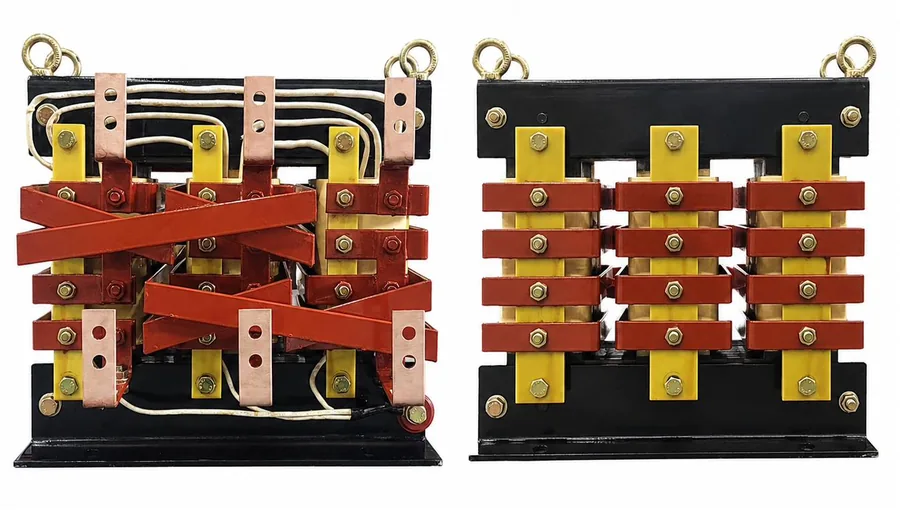
PECO Harmonic Energy Recycling Transformer
- Low-heat winding structure — Korean Patent 10-2546570
- Nine-point zig-zag interconnection
- Phase load balancing
- Fixed 4 % voltage difference, no tap changing
- Transformer efficiency typically 99.8 % or higher
- H-class insulation, AN cooling
Protection & Support
| Device | Function |
|---|---|
| EOCR | Overload and overcurrent detection |
| ATS | Transfer between Saving and By-pass paths |
| Control Circuit | Processing of protection signals and operating commands |
| SPD | Surge and transient overvoltage protection |
| MCCB · Fuse | Control power and circuit protection |
| CPT | Single-phase supply for the Control Circuit |
| Thermostat | Fan control by preset temperature |
| Fan | Cabinet ventilation |
| Digital Meter | Display of operating voltage, current and power |
The transformer saves. The system protects.
No consumable parts. No software. Three-year warranty on the transformer.
Two Simple Power Paths
Saving Mode
Input → Harmonic Energy Recycling Transformer → Load
Normal energy-saving operation.
By-pass Mode
Input → Direct By-pass Path → Load
Direct supply to the load, without passing through the core transformer.
Overload protection
The EOCR monitors load current. When the preset overload condition is detected, the EOCR contact operates the Control Circuit, which commands the ATS to transfer the load from the Saving path to the By-pass path.
Ventilation
Cabinet ventilation operates independently. The thermostat starts the fan when the preset internal temperature is reached.
Project option
A separate overtemperature alarm is available as a project option.
The same capability makes measurement possible.
Because the load can be transferred between the Saving and By-pass paths at the same site, on the same meter, the effect of PECO can be measured directly rather than estimated. Most passive energy-saving equipment cannot be evaluated this way.
See how savings are measuredMeasurement & Verification
We Do Not Publish a Saving Percentage. We Publish the Method.
Energy savings depend on load composition, operating hours, phase balance and harmonic conditions. A single published figure, applied to every installation, would be meaningless — and in this industry it is usually a warning sign.
What we commit to is the measurement method.
01
Measured in kWh, at the billing meter
Not instantaneous kW. Not a simulation. Accumulated energy over comparable periods, measured at the point the utility measures.
02
Same site, same meter
The load is operated alternately through the Saving path and the By-pass path. Comparison is made on the same installation, with the same connected equipment, in the same season. No modelled baseline is required.
03
Continuous remote monitoring
Where our partners operate remote metering, consumption is logged continuously from before installation and reported to the customer on an agreed schedule.
Reports are prepared for each customer individually. PECO does not publish customer names, site data or project results.
Designed for Long-Operating Facilities
Hotels & Resorts
HVAC and chillers, pumps, refrigeration, commercial kitchens, laundry, elevators, lighting and guest-service loads run for long hours and vary continuously with occupancy.
PECO Powersaver is installed at the distribution level. No guest-facing equipment is modified.
Over more than ten years of installations — the majority in hotels, where acoustic requirements are among the strictest of any facility type — no noise-related issue has been reported.
Industrial Facilities
Compressors, large inverter-driven motors, pumps, fans, forging and mixed production loads. Some of our strongest measured results have come from facilities of this type.
Shopping Malls & Retail
HVAC, escalators, refrigeration, tenant panels and lighting.
Office & Commercial Buildings
HVAC, elevators, lighting, office electronics and utility systems.
Delivered across Asia, the Middle East, Europe and South America
| Region | Notes |
|---|---|
| Republic of Korea | Manufacturing base — zig-zag energy-saving transformers since 2005 |
| United Arab Emirates | International hotel and resort groups |
| India | International hotel chains and commercial complexes |
| Thailand · Malaysia | Commercial and industrial facilities |
| Italy | Continuing supply. Partner-operated projects with remote monitoring |
| South America | Commercial and industrial facilities |
Customer names, site locations and project results are confidential, and are shared only under a non-disclosure agreement during technical review.
Product Range
The complete standard range — 100 kVA to 3,000 kVA — is assessed by TÜV SÜD.
- 39 models, 100 to 3,000 kVA
- ATS Type · ATS & ACB Type
- Rated input 380 / 400 / 415 / 440 / 480 VAC
- Indoor, IP 42, three-phase three-wire
- Customised enclosure configuration
Built by ATECELECTRIC
Transformer and power reactor manufacturing since 1999. Zig-zag energy-saving transformers since 2005. In-house design of PECO Powersaver since 2018.
- Electrical design
- Core and coil manufacturing
- Zig-zag winding
- Cabinet assembly
- Control Circuit wiring
- Inspection and testing
Discuss Your Project
Send your transformer rating and single-line diagram. We review technical suitability before proposing anything.