
PECO Powersaver System
A single cabinet containing one energy-saving transformer and the protection, switching and indication equipment that keeps it running safely.
One Transformer, Fully Protected
PECO Powersaver is a complete, factory-assembled system built around the PECO Harmonic Energy Recycling Transformer. The transformer performs the energy-saving function. Everything else in the cabinet exists to protect it, switch it, supply its control circuit or display its operating values.
The transformer is connected in series at a single point in the low-voltage distribution system, and is built to add almost no resistance of its own. No connected equipment is modified.
- 100–3,000 kVA
- Three-phase, three-wire
- Indoor, IP 42
- 380 / 400 / 415 / 440 / 480 VAC
- Passive operation
The transformer saves. The system protects.
Position in the Distribution System
Between the main circuit breaker and the sub-distribution boards, in series. The system neutral bypasses the unit and connects directly to the boards. The rating of the unit is normally matched to the rating of the facility transformer, so that one installation covers the whole system.
- Main Transformer
- Main Circuit Breaker
- PECO Powersaver
- Distribution Boards
- Facility Loads
The system neutral bypasses the unit and connects directly to the distribution boards.
Installation, commissioning and outage planning are covered in How It Works
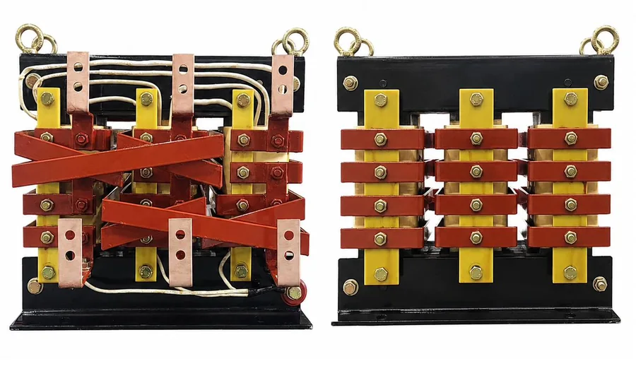
PECO Harmonic Energy Recycling Transformer
A three-phase zig-zag autotransformer, designed and manufactured in-house, and built above all to add as little resistance and heat as possible to the circuit it sits in.
- Full zig-zag main winding with a separately wound reverse auxiliary winding — 100 turns plus four, where the conventional arrangement uses 96 plus four
- The two windings tied at both ends, so the auxiliary path carries more current at lower resistance than its own conductor would allow
- Nine zig-zag transition points, where a conventional arrangement has six
- Fixed 4 % voltage difference, no tap changing
- Phase load balancing
- Transformer efficiency typically 99.8 % or higher
- H-class insulation, allowable winding temperature 130 °C
- AN (air natural) cooling
- Korean Patent No. 10-2546570
Two Power Paths
Saving
Power passes through the Harmonic Energy Recycling Transformer. This is the normal operating position.
By-pass
The transformer is out of circuit and the facility is supplied directly — exactly as it was before installation.
Transfer is made by an automatic transfer switch. Under an overload condition detected by the EOCR, transfer to By-pass is automatic and occurs under load. Deliberate transfer for maintenance or measurement is performed at no load, during a scheduled window.
Because the By-pass path restores the original supply arrangement exactly, the installation can be reverted at any time.
What Surrounds the Transformer
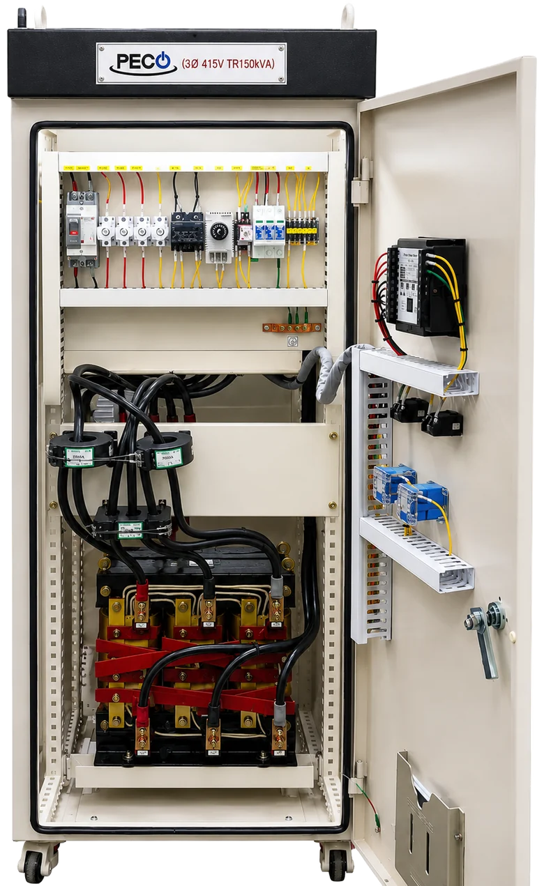
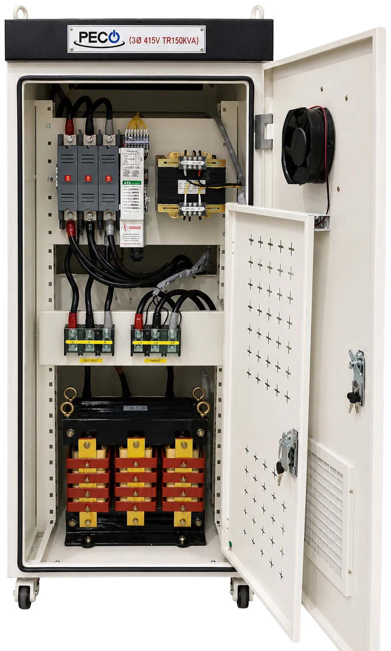
The rear of the cabinet carries the switching, protection and control equipment. The transformer sits at the base, below the input and output terminal blocks.
- Automatic transfer switch and control wiring, upper section
- Control power transformer, manufactured in-house
- Separately marked INPUT and OUTPUT terminal blocks
- Harmonic Energy Recycling Transformer at the base, on its own mounting frame
- Ventilation fan and filtered grille in the rear door
| Device | Function | Component |
|---|---|---|
| ATS | Transfer between the Saving and By-pass paths | Automatic transfer switch, CE-marked, rated per model |
| EOCR | Overload and overcurrent detection | Schneider Electric EOCR series |
| Control Circuit | Processing of protection signals and operating commands | — |
| MCCB · Fuse | Control power and circuit protection | LS Electric Metasol series, to IEC 60947-2 · gG fuse to IEC 60269 |
| SPD | Surge and transient overvoltage protection, Class II | Vitzro VE-40K, to IEC 61643 |
| CPT | Control power supply, 415 / 220 V | Manufactured in-house |
| Digital Meter | Display of operating voltage, current and power | KDX series, 50 / 60 Hz |
| Thermostat · Fan | Cabinet ventilation control | Rated per enclosure size |
Component makes and models are listed in the product manual delivered with each unit and are confirmed per project. Selection may be adapted to customer specification or destination market requirements.
The digital meter displays operating electrical values for verification. It is not an active energy-analysis or power-control system.
Configured for the Project
Enclosure arrangement, protection configuration and indication are specified per project rather than sold from a fixed catalogue. Units supplied to different markets are built to the practice of that market — including phase colour coding, enclosure footprint and terminal arrangement.
Custom configuration is practical because ATECELECTRIC designs and manufactures the transformer, winds the coils and assembles the cabinet in one facility.
- Overtemperature alarm
- Remote status contacts
- Project-specific indication
- Customer-specified protection devices
- Regional enclosure configuration
- Customised terminal and cable entry arrangement
Third-Party Assessed by TÜV SÜD
Under the Low Voltage Directive a manufacturer may self-declare conformity. ATECELECTRIC obtained third-party attestation voluntarily.
| Certification body | TÜV SÜD Product Service GmbH, Munich, Germany |
|---|---|
| Document | Attestation of Conformity No. N8A 103329 0002 Rev. 00, issued 21 September 2020 |
| Test report | No. CPSA01330420 |
| Directive | Low Voltage Directive 2014/35/EU |
| Tested to | EN 62477-1:2012/A1:2017 |
| Models covered | PECO100 – PECO3000 · 39 models · the complete standard range |
| Rated input voltage | 380 / 400 / 415 / 440 / 480 VAC, three-phase |
| Rated frequency | 50 Hz |
| Protection class | I |
| Assembly | Built in accordance with IEC 61439 |
| Quality · Environment | ISO 9001 · ISO 14001 |
| Patent | Korean Patent No. 10-2546570 |
Certification scope varies by model, rating and destination market. Applicable certificates are confirmed at project stage. Units for markets outside the scope above are built and certified to the requirements of the destination market.
Ratings, Dimensions and Technical Data
Model range, dimensions, weights, efficiency figures and site requirements are listed on the specifications page.